Medical devices aren’t getting simpler. Today’s products routinely combine rigid structures with soft-touch ergonomics, environmental sealing, strain relief, and compact functional architectures-often with tubing, wires, sensors, electrodes, and connectors routed through tight packaging envelopes. Overmolding is one of the most powerful tools available to reduce part count and improve reliability in a medical environment.
But overmolding success isn’t defined by whether you can make a few good parts. It’s defined by whether you can build a repeatable, high-volume process that controls the interface, protects critical-to-quality features (CTQs), and supports inspection at production speed.
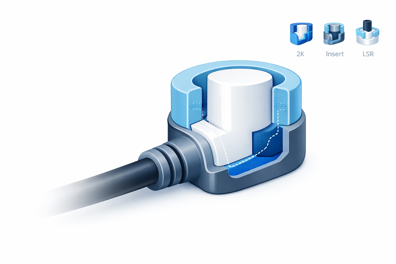
This guide breaks down the three main production paths-two-shot (2K) overmolding, insert/pick-and-place overmolding, and LSR overmolding-and explains how an engineer should choose between them. It also outlines the scalable DFM approach EPTAM uses to connect design intent to capability at volume, including automation and inspection strategies enabled by proprietary robotic production systems.
Overmolding fundamentals engineers should decide early
What problem is the overmold solving?
“Overmold” describes many different functional goals. Start by stating the engineering requirement in plain terms-because that requirement determines the right materials, interface geometry, and production path:
- Seal performance: ingress protection, leak resistance, or controlled compression at an interface
- Ergonomics: grip, tactile feel, vibration damping, user comfort
- Strain relief: controlled bend radius and pull-out resistance for cables, wires, and tubing
- Encapsulation/protection: shielding sensitive features from handling, moisture, or contamination (as appropriate)
The interface is the product
Overmolding is an interface engineering problem. At volume, outcomes are driven by four linked decisions:
- Bond strategy: chemical adhesion, mechanical interlock, or both
- Shutoff/parting strategy: how you prevent flash where flash cannot exist
- CTQ definition + inspection plan: what you will measure, and how fast
- Process window stability: how sensitive the design is to normal variation in molding conditions
If one of these is left “to be solved in the tool,” programs often work in prototype builds and then break during scale-up-when cycle time pressure, material lot variation, and real production throughput expose narrow margins.
The three production paths – and when each wins for overmolding for medical devices
Path 1: Two-shot (2K) overmolding
What it is: Two materials are molded sequentially within a single, integrated system (often via rotary platen, indexing, or transfer concepts). The second material is applied to a first-shot substrate with controlled registration. This overmolding approach assists with several factors in medical environments.
Where it shines:
- High-volume programs where eliminating handling steps improves repeatability
- Tight registration requirements between materials (grip zones, seals, tactile features)
- Designs where material-to-material bonding must be consistent and process-controlled
Engineering watch-outs:
- Material pairing and adhesion: “Compatible” is not a marketing term; it’s a process-and-interface reality. Bond outcomes depend on resin chemistry, melt temperature, timing, and surface condition.
- Differential shrink and warpage: Two materials with different shrink/CTE behavior can move CTQs unless the part is designed to manage constraint and cooling symmetry.
- Gate and flow planning: Where the second shot enters can shift knit lines, create stress, or introduce cosmetic risk right at the bond boundary.
Scalability note: Two-shot often delivers the best repeatability because it reduces touches and time between operations. It is also a strong candidate for automation and inline inspection because the process can be built as a tightly controlled cell.
Path 2: Insert (pick-and-place) overmolding
What it is: A pre-molded plastic substrate or component is loaded into a second mold where the overmold material is applied. The “insert” may be a rigid plastic core-or a more complex subassembly.
Where it shines:
- Programs with multiple variants or evolving designs where flexibility matters
- Cases where the rigid component already exists (or must be made separately for other reasons)
- Applications where the insert includes tubing, wires, sensors, or connectors that must be positioned prior to overmolding
Engineering watch-outs:
- Placement repeatability: At volume, small insert seating shifts create flash, thin spots, or dimensional drift at CTQs.
- Insert condition: Contamination, moisture, or handling damage changes bonding and cosmetics. For some material pairs, surface energy and cleanliness dominate outcomes.
- Thermal state of inserts: Insert temperature affects wetting, bond formation, and cycle stability. Uncontrolled temperature becomes uncontrolled variability.
- Protection of delicate subassemblies: Flexible tubing and wire bundles can be pinched, misrouted, or distorted unless the design supports robust fixturing and load paths.
Scalability note: Insert overmolding scales best when the part is designed for repeatable, automation-friendly loading-including orientation features, robust seating geometry, and poka-yoke elements that prevent wrong placement.
Path 3: LSR overmolding
What it is: Liquid silicone rubber (LSR) is molded onto or around a rigid thermoplastic component (or integrated into a multi-material system). LSR is often selected when sealing performance, compliance, or environmental robustness is central to device function.
Where it shines:
- Sealing interfaces that must be consistent over many cycles or under chemical exposure
- Compliant features that control compression and reduce leak risk
- Soft interfaces needed for user interaction, damping, or protection
Engineering watch-outs:
- Bond method: Depending on the application, bonding may be achieved via self-bonding LSR grades, surface prep, or primers. Each route has implications for validation, long-term stability, and process controls.
- Flash sensitivity: LSR is unforgiving of poor shutoffs and venting choices. Flash can be a yield killer-especially when it appears in sealing lands or functional interfaces.
- Seal geometry is a CTQ: Compression, gland design, and constraint must be engineered with the rigid plastic geometry as one system-not as two separate parts.
Scalability note: LSR overmolding is highly scalable when shutoffs, venting, and inspection are designed upfront-and when automation reduces handling variability of the rigid substrate.
A decision framework engineers can actually use when considering overmolding in medical device manufacturing
Overmolding path selection should be driven by a small set of inputs that correlate strongly with cost, yield, and schedule at scale. Here’s how to consider the overmolding path for your medical environment.
- Volume + ramp profile: Is this a steady high-volume program, or a staged ramp with variants?
- Interface criticality: Is the overmold a cosmetic feature, a seal, a strain relief, or a safety-critical function?
- Insert complexity: Are you overmolding a rigid plastic core, or a subassembly with tubing/wires/sensors that must be positioned precisely?
- Material constraints: Chemical exposure, sterilization/cleaning environment, optical needs, and allowable particulate/cosmetic risk
- Inspection reality: What must be checked-flash-free zones, seating, presence/absence, bond-line stability proxies-and can it be verified at production speed?
Practical guidance:
- Two-shot tends to win when volume is high, registration is tight, and minimizing handling variability is worth the tooling complexity.
- Insert overmolding tends to win when the insert is a complex subassembly (tubing/wires/sensors), when variants are likely, or when process flexibility matters.
- LSR overmolding tends to win when sealing or compliance is central-and when the team is ready to engineer shutoffs, venting, and inspection around silicone realities.
Scalable DFM for overmolding: what changes when you go from “works” to “runs”
Scaling overmolding is rarely limited by “molding skill” alone. It’s limited by whether the design can be controlled and verified under real production constraints. EPTAM’s scalable DFM approach focuses on four pillars that connect design intent directly to high-volume capability.
DFM Pillar 1: Define CTQs like you plan to inspect them at production speed
CTQs in overmolding commonly include:
- Flash-free zones (sealing lands, optical interfaces, cosmetic edges, functional mating surfaces)
- Bond performance expectations (where adhesion matters vs where interlock carries load)
- Seal geometry (compression targets, gland dimensions, controlled squeeze)
- Registration and alignment (datums that drive assembly or instrument interfacing)
The principle is simple: if it can’t be inspected consistently at speed, it can’t be controlled at volume. DFM must include how each CTQ will be measured-especially when throughput pressures make “slow inspection” unrealistic.
DFM Pillar 2: Engineer the bond strategy-don’t “hope” for adhesion
Bonding in overmolding is rarely binary. It’s typically a combination of:
- Chemical adhesion driven by material pairing and process conditions
- Mechanical interlock driven by geometry that resists peel, pull-out, and shear
For complex medical assemblies, bond strategy often expands to include strain relief and load-path design. When tubing, wires, or sensor leads are present, the overmold may need to provide controlled bend radius, pull-out resistance, and protection from sharp transitions that concentrate stress. Engineers should ask: Where does the load go during use? During drop? During repeated flex? Then design the overmold geometry to manage those loads-without creating thin sections that are difficult to fill or difficult to inspect.
DFM Pillar 3: Shutoffs and parting lines-the real yield battle
Flash is one of the most common reasons overmold programs struggle at scale. The engineering root causes are usually geometric:
- Shutoffs placed too close to CTQs (any wear or minor mismatch becomes scrap)
- Fragile edges that wear quickly, changing flash behavior over time
- Parting lines routed through sealing lands, optical zones, or functional datums
Scalable DFM treats shutoff strategy as a first-class design problem. That means planning where the parting line should live, how shutoffs will be supported, and how the design will tolerate long-term production wear-while still delivering the required cosmetics and function.
DFM Pillar 4: Design for a stable process window
Many scale failures are process-window failures: parts are acceptable only in a narrow band of settings. Common contributors include abrupt wall transitions near the interface, marginal fill conditions, and gating that forces knit lines or stress into critical zones.
Scalable DFM aims to widen the stable window by aligning:
- Wall strategy and transitions near the interface
- Gate placement and flow direction relative to CTQs
- Material selection and shrink behavior relative to registration requirements
Designing for automation: how robotics changes overmolding outcomes
As medical device assemblies incorporate more tubing, wiring, and sensing elements, manual handling becomes a variability source. EPTAM’s approach emphasizes designing parts and processes that are automation-ready from the beginning-supported by proprietary robotic systems used for production handling and inspection across services.
Automation-ready geometry
Design features that often improve high-volume stability include:
- Orientation features that make correct loading unambiguous
- Robust seating geometry that prevents “almost seated” conditions
- Lead-ins and poka-yoke elements that reduce insertion force variability
- Pick surfaces and handling zones that protect cosmetic and sealing areas
Complex assemblies with tubing, wires, and sensors
At volume, failures often come from inconsistent routing, seating depth variation, crush damage, or contamination introduced during handling. Robotics changes the outcome by enabling consistent routing and fixturing, repeatable insertion depth, and controlled timing-reducing the variability that drives intermittent defects. All these overmolding factors should be weighed carefully as robotics are implemented in your medial manufacturing environment.
Inspection at production speed: building quality into the cell
Overmolding quality can’t rely on “end-of-line discovery,” especially when the defects are intermittent or occur at interfaces. Modern high-volume production often requires in-line inspection integrated with automation.
Common overmold inspection targets include:
- Flash detection in defined no-flash zones
- Short shot / fill anomalies and cosmetic defects
- Presence/absence checks for inserts or subassembly elements
- Alignment and seating verification before and/or after molding
The key engineering point: inspection must be designed into the process. That means CTQs, datums, and access for vision or measurement are part of DFM-not an afterthought.
Where EPTAM fits: overmolding as a scalable system, not a single process
Choosing the right overmolding path is important. Making it scalable is the differentiator. EPTAM’s strength is connecting DFM for overmolding directly to high-volume process capability-and reinforcing that capability with proprietary robotic systems that support repeatable handling and production-speed inspection across services.
When design, process strategy, automation, and inspection are planned together, teams reduce redesign loops, stabilize yield earlier, and build a more resilient path from “first parts” to sustained production.

Conclusion – Overmolding for Medical Devices
The right overmolding path depends on interface physics (bond and flash control), assembly complexity (including tubing, wires, and sensors), and the practical reality of inspection at throughput. Two-shot, insert overmolding, and LSR overmolding can all be the “right answer”-but only when the design is engineered for repeatability, verification, and scalability.
If you want overmolding to deliver on its promise-fewer parts, fewer failure modes, and better device robustness-bring manufacturing into the design decision early. That’s where scalable DFM, automation-ready geometry, and production-speed inspection planning have the most leverage.